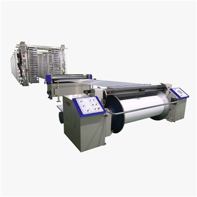
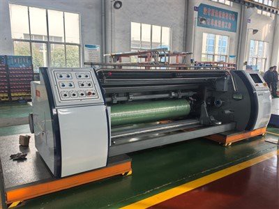
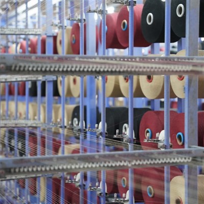
A warp beam winding machine mainly consists of two parts: the warp beam frame (or warp head frame) and the warp head. Its process involves three key structures: the warp head frame with the warp heads, the warp reed for separating or arranging warp yarns (in some models, this is located between the warp head and the warp beam frame), and the warping mechanism (i.e., the winding mechanism of the warp head) that precisely winds the yarn onto the warp beam.
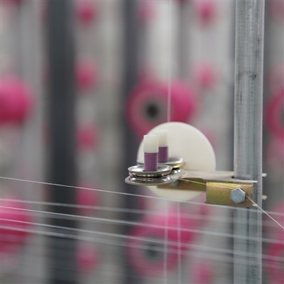
The core design requirement of a warp beam winding machine is to achieve constant tension and constant speed winding. The tension control device on the warp beam frame (such as a pneumatic warp tension control device) must automatically maintain a constant and uniform unwinding tension for the warp yarns on each warp beam; the winding mechanism of the warp head must wind the warp yarns at a constant speed and constant tension, while simultaneously applying winding pressure to the warp beam through pressure rollers (such as pneumatic rollers). The main control requirements include: stable tension, avoiding large or abrupt changes; real-time adjustment of winding tension and stiffness; stable overall linear speed with smooth acceleration and deceleration; consistency between actual and target values; and real-time adjustment of the traction roller's speed and feed rate frequency, following the winding roller's speed changes.
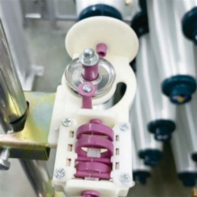
For performance optimization of the twinning machine, several patented design improvements exist, such as: tension adjustment devices (e.g., adjusting the tension frame position via a worm gear mechanism), protective devices that automatically clamp the broken yarn, and material rack structures integrating cleaners (e.g., cleaning arms with sandpaper sliding shafts).